b-science.net
FAQ Use Cases Blog About Us Register Log In


2025-12-16
Patent Analysis Switch to Visual Summary

Triweekly Patent Update – Free Version

Lithium-ion batteries – electrolytes – solid & semi-solid

LG ENERGY SOLUTION / UNIVERSITY OF CALIFORNIA / WO 2025234725 A1

ALL-SOLID-STATE BATTERY COMPRISING SILICON-CONTAINING LAYER

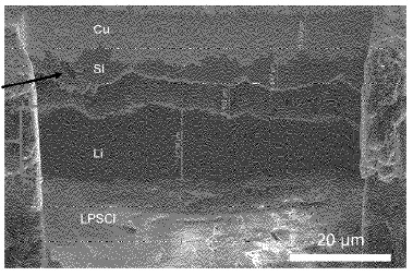
An anode-free all-solid-state battery was developed featuring an amorphous silicon layer on a copper current collector. The silicon layer exhibits a thickness of up to 500 nm (see Figure), resulting in Ns/P ratios (charge capacity of silicon layer to positive electrode) of less than 0.3.

The battery comprises a Li6PS5Cl (LPSCl) solid electrolyte separator and a positive electrode composite of NMC811 with LPSCl and vapor-grown carbon fiber (VGCF) (mass ratio : 66 : 31 : 3, 3 mAh/cm2 loading). Amorphous silicon (500 nm) was deposited on Cu via sputtering. This stack was pressed at 370 MPa prior to cycling, while a stack pressure of 5 MPa was maintained during cycling.

During initial charging, silicon lithiation occurred up to 3.7 V (0.25 mAh/cm2), forming amorphous LixSi1-x (0.5<x<0.79) with composition Li0.7Si0.3. Subsequent lithium metal plating (2.75 mAh/cm2) formed a dense lithium layer on the pre-lithiated silicon substrate. The lithiated silicon layer persists throughout cycling without further silicon participation.

Rate performance testing in the all-solid sulfide electrolyte cells exhibits stable cycling up to C/5 (0.6 mA/cm2). Thin-film cells with LiPON solid electrolyte demonstrate critical current densities up to 5.0 mA/cm2, representing a five-fold improvement compared to bare Cu current collectors.

LG ENERGY SOLUTION / UNIVERSITY OF CALIFORNIA / Patent Image
Takeaway: Amorphous silicon seed layers with controlled Ns/P ratios (<0.3) enable uniform lithium metal nucleation and growth in anode-free solid-state batteries. Complete silicon lithiation during initial charging prevents subsequent silicon participation, eliminating pulverization and short-circuit issues observed at higher Ns/P ratios (>0.3). The lower critical current density for Li6PS5Cl compared to LiPON indicates that commercial development strategies combining Si-based materials with sulfide electrolytes require comprehensive product development approaches incorporating synergies between multiple sulfide R&D concepts.

Lithium-ion batteries – negative electrode (excluding Li metal electrodes)

KK Toyota Jidoshokki / JP 2025171661 A

Method for producing a negative electrode active material containing silicon clathrate II

Na ingots were cut into ≈5 mm pieces and mixed with Si powder in a Wonder Crusher (Si amount: 102 parts by mass per 100 parts Na). The Na ingots were added in three portions, followed by mixing for 1 min for each portion. The resulting mixture was placed in a stainless steel container, evacuated, and heated under argon flow (420°C, 40 h), which resulted in a Na-Si alloy.

AlF3 particles were sieved with a 32 µm mesh to remove fine particles, followed by sieving with a 75 µm mesh to remove coarse particles, which resulted in an AlF3 classified material with a D50 particle size of 56.1 µm (D10: 38.9 µm, D90: 80.2 µm).

The AlF3 classified material was mixed with the Na-Si alloy (AlF3 amount: 50-100 parts by mass per 100 parts Na-Si alloy). This mixture was placed in a stainless steel container, evacuated, and heated under argon flow (350°C, 60 h), resulting in silicon clathrate II.

The material exhibits a silicon clathrate II / silicon clathrate I ratio of 14.0 as measured by XRD (X-ray diffraction), as compared to 0.74 for a comparative material prepared without classification of AlF3 particles (D50: 75.1 µm, D10: 37.6 µm, D90: 138.6 µm).

Takeaway: Selective silicon clathrate II formation is achieved by controlling the particle size distribution of the AlF3 precursor. Silicon clathrate II exhibits a porous structure that offers limited volume changes upon cycling.

Lithium-ion batteries – positive electrode

L&F Co., Ltd. / KR 20250160740 A

Transition Metal Precursor and Cathode Active Material Prepared from the Same

A high-nickel Ni0.89Co0.04Mn0.07(OH)2 precursor with center-concentrated buffer pores was synthesized. Polypropylene particles (3 μm diameter) were added to a mixed metal sulfate solution (Ni : Co : Mn molar ratio of 0.89 : 0.04 : 0.07, 2.0 M, 50°C). The solution was stirred at 400 rpm while sodium hydroxide was added to maintain pH at 11.5-11.6, forming precursor seeds. The pH was decreased stepwise to 11.0-11.2, 10.7-10.9, and 10.3-10.5 while stirring speed increased to 1,000 rpm (5 h).

The dried precursor exhibits secondary particles (≈12 μm) with polypropylene concentrated in the core region. The precursor was mixed with lithium hydroxide (Li : transition metal molar ratio of 1.03 : 1) and sintered (5°C/min to 750°C, 17 h) to obtain LiNi0.89Co0.04Mn0.07O2.

During sintering, polypropylene decomposes to form buffer pores (≈3 μm) concentrated in the particle center (see Figure). Primary particles in the outer region exhibit radial crystalline structure oriented from center to surface.

In half-cells (lithium metal negative electrode, 0.5 C charge / 1 C discharge, 45°C), the material exhibits a discharge capacity of 210 mAh/g and capacity retention of 96.3% after 50 cycles, as compared to 210 mAh/g and 92.1% for material without buffer pores. The material exhibits 3.38 vol% of particles <1 μm after pressing, as compared to 5.71 vol% for comparative material.

L&F Co., Ltd. / Patent Image
Takeaway: Sacrificial polypropylene particles concentrated in the precursor core via controlled stirring speed decompose during sintering to form buffer pores in high-Ni NCM, relieving internal stress and preventing particle cracking.

Fuel cells (PEMFC / SOFC / PAFC / AEMFC) – electrochemically active materials

TOYOTA MOTOR / WO 2025239304 A1

IONOMER

A modified ionomer was developed for polymer electrolyte membrane fuel cell (PEMFC) cathode catalyst layers with enhanced oxygen transportability.

The ionomer comprises perfluorocarbon sulfonic acid polymer (Nafion EW : 1100) with sulfonic acid functional groups. A modifying layer containing 1,3,5-triazine forms ionic bonds with the acidic functional groups on the ionomer surface.

The ionomer material and modifier containing 1,3,5-triazine were mixed in water/ethanol solvent using an ultrasonic homogenizer and stirrer (15 min). The 1,3,5-triazine content was 3 mass% relative to total ionomer mass, corresponding to 34 mol% relative to acidic functional groups.

The modified ionomer was combined with platinum catalyst (48-50 mass% Pt on acetylene black support) to prepare cathode catalyst ink. The ink was coated onto polytetrafluoroethylene (PTFE) substrate and dried to form a catalyst layer (5-30 μm thickness, 0.1-0.6 mg-Pt/cm2). Membrane electrode assemblies (MEA) were fabricated using Nafion NR211 electrolyte membrane.

Performance testing (80°C, 80% relative humidity, 3.2 A/cm2) exhibits a cell voltage improvement of 64 mV as compared to unmodified ionomer MEA (absolute cell voltages were not disclosed). The electrode catalyst layer exhibits proton transport resistance of 0.043 Ω·cm2 and oxygen diffusion resistance of 13 s/m, as compared to 0.062 Ω·cm2 and 15 s/m for unmodified ionomer.

Takeaway: Modifying ionomer acidic functional groups with nitrogen-containing cyclic organic compounds such as 1,3,5-triazine enhances cell voltage, oxygen transportability and proton conductivity in PEMFC cathode catalyst layers.

Other Categories (Excel lists are included for paid users)

  • Lithium metal batteries (excluding Li-S, Li-Air): Excel list
  • Lithium-air batteries: Excel list
  • Lithium-ion batteries – electrolytes – liquid: Excel list
  • Lithium-ion batteries – separators: Excel list
  • Lithium-sulfur batteries: Excel list
  • Na-ion batteries: Excel list