-
Assessment of Companies
-
Author comments are displayed in maroon.
-
Sample Assessment – Anonymized Cell Manufacturer
Shortened Version: Slide Deck (6 Slides)
-
The assessment below is reproduced from a current review chapter, with the company name, all
patent publication numbers, patent links and other identifying references removed. All figures
shown here are b-science.net analyses of the underlying patent portfolio.
The identified company and the complete chapter are included in the full version.
-
Organization Profile
The company is a vertically integrated lithium-battery manufacturer. It produces cells, modules, packs and energy-storage systems in-house, and has built
a dedicated semi-solid-state cell line.
-
Technology Assessment
(Assuming Patents Were Filed with Intent to Launch Products)
Latest Identified Benchmarking Data:
Semi-solid (hybrid solid–liquid) platform – company-demonstrated: The first-generation high-nickel
semi-solid prismatic cell reaches 270 Wh/kg and has been in small-scale production since December 2025,
installed in a model of a European passenger-vehicle brand; C-sample batch trial began in November 2025 on
the dedicated semi-solid line. The cathode is high-nickel; the anode is not disclosed (graphite probable),
and cycle life, charge and discharge protocols are not reported. The second-generation high-nickel cell
reaches 342 Wh/kg, development complete, installed and flight-tested in an eVTOL aircraft; a 360 Wh/kg pouch
cell was sampled to a state-owned eVTOL program (September 2025). A mid-nickel cell at 245 Wh/kg is
targeted for mass production in October 2026, and a 100 kWh pack at 188 Wh/kg system-level energy density
with peak 6 C charging for the third quarter of 2026 (not yet demonstrated). Cells announced for
low-altitude aircraft sustain 5 C continuous and 8 C peak discharge and are stated to meet DO-311A. Process
metrics: electrolyte transfer rate raised from ≈20% to over 95% (100% = complete release of the cast layer
onto the electrode), HIPOT (high-voltage insulation test) yield +10% and safety performance +50%
(September 2025); separator ionic conductivity +10%, 200 °C shrinkage –20%, thermal-runaway onset +5 °C and
field voltage-difference defect rate –18.5% (January 2026). No demonstrated cell was identified that uses the
lithium-metal architecture the patents pursue.
All-solid-state sulfide program – company-demonstrated: A 20 Ah sulfide all-solid-state cell sample
reaches 380 Wh/kg with a cycle life above 450 cycles (retention threshold, rate and temperature not disclosed);
the all-solid-adapted cathode exceeds 220 mAh/g with over 1,200 stable cycles, and the sulfide electrolyte
retains over 93% of its ionic conductivity after 4 h of high-humidity exposure (September 2025). Nothing appears
to be in production yet. This track is not discussed further below, but is available in the adjacent Excel file.
Figure X-1: Multidimensional visualization of semi-solid Li-ion battery cell product development &
up-scaling efforts

Unique Capabilities:
Semi-solid (hybrid solid–liquid) platform: The distinctive edge is process compatibility, not a new
chemistry: the solid-electrolyte layer is transfer-printed onto electrodes on existing liquid-cell lines, at a
transfer rate lifted from roughly 20% to over 95%. First-generation cells are in small-scale production; the
lithium-metal build visible in the patents is not yet made.
All-solid-state sulfide program: Here the edge is full-stack in-house development rather than a proven
cell: sulfide electrolyte, all-solid-adapted cathode and cell are developed internally, and the thermal-composite
stacking step already running in volume is intended to replace isostatic pressing.
Leap of Faith:
Semi-solid platform: That the safety margin demonstrated for the transfer-printed coating in cells still
filled with volatile carbonate in recent patent filings survives substitution by non-flammable in-situ polymerized
electrolyte against a lithium-metal anode. The fluorinated ionic liquid will not cause excessive SEI formation in
contact with the lithium-metal anode. Underlying Scientific Hypothesis: Because the
triallyl-phosphate-crosslinked acryloyl-morpholine network immobilises the EMIm-TFSI plasticizer at 10–18 mass%
rather than leaving a free liquid able to reflow into the volume vacated by stripped lithium, the anion-derived
interphase set at first contact stays self-limiting as the lithium surface roughens (Concept 3, avoidance of
excessive SEI formation).
All-solid-state sulfide program: That the four-layer coating sequence on porous silicon keeps the
silicon–sulfide interface conducting through repeated volume change as cells scale from the demonstrated 20 Ah,
380 Wh/kg sample to the targeted 60 Ah-plus, 400 Wh/kg format.
Underlying Scientific Hypothesis: Because the porous framework absorbs expansion internally while the
ordered oxide, carbon, sulfide and conductive-polymer shells keep electron and ion paths separate and unbroken
(Concept 4), the silicon–sulfide interface can survive automotive cycle counts.
Technical Approach & Differentiation:
Semi-solid platform: The differentiating decision, publicly framed as safety without added manufacturing cost, is to keep the semi-solid cell on the existing liquid line. Rather than direct-coating the layer onto the
electrode, whose coating-weight scatter it would inherit, it is cast on a flat carrier at metered areal density and
hot-press-transferred; Concept 1 (EPO / Google) is the most plausible basis for the transfer-printing process the company has publicly disclosed (linkage unconfirmed). The other concepts serve it: epoxy-silane anchoring removes the polyolefin
separator (Concept 2), a non-flammable electrolyte replaces the volatile carbonate (Concept 3), a seconds-long UV
cure replaces the multi-hour bake (Concept 5). The crux: no disclosed cell was identified yet that combines the
transferred interface, the non-flammable electrolyte and lithium metal.
All-solid-state sulfide program: The calculated risk is to move the solid-electrolyte interface inside the
anode particle. Rather than blending electrolyte into the anode and holding solid–solid contact by stack pressure,
porous silicon is coated in sequence – oxide, carbon, argyrodite sulfide, then an outer conductive polymer –
building ion and electron paths inside the particle (Concept 4, EPO / Google). That choice underwrites the
production route: cascaded roll densification (EPO / Google) in place of 300 MPa isostatic pressing,
plus an anode-free variant the company is developing to cut cost (EPO / Google). The open question: whether an interface engineered at particle scale holds at cell
scale.
Timeline Feasibility:
Semi-solid platform: The ramp is manufacturing-led: first-generation cells left the production line in small batch in December 2025, after a November 2025 C-sample trial on the dedicated line; the mid-nickel cell is targeted
for mass production in October 2026, a 100 kWh pack for the third quarter, series production for September 2026 and
large-scale supply to a European premium sub-brand for 2027. Second-generation development targets 400 Wh/kg, a third generation 450 Wh/kg by 2028. One revision: the first-generation cell was described in July 2025 as a 140 Ah pouch at 300 Wh/kg and, from September 2025, as a prismatic cell at 270 Wh/kg. Because the process needs no new
equipment and lithium metal is not on the critical path (graphite and/or graphite with added Si-based active material
likely is used initially in the anode), a shortfall there would delay later generations rather than the 2026 ramp.
All-solid-state sulfide program: The roadmap has been restated. In September 2025 the company placed a
70 Ah-plus, 500 Wh/kg all-solid cell in 2028; in May 2026 it set three phases – a 20 Ah system at 380 Wh/kg by
end-2025 (reached as a sample), a 60 Ah-plus sample at 400 Wh/kg by end-2027, and a 70 Ah-plus sample above 500 Wh/kg in 2030 – with demonstration vehicle installation from 2027 and mass production in high-performance applications in 2030. Cell cost remains 5–10 times that of liquid electrolyte cells. No mass-production date is
identified for a specific all-solid-state product, and the stacking process meant to carry it is described by the
company as pre-research.
Scale-Up Risk Factors:
Semi-solid platform: The principal risk: holding the transferred ≈2 μm layer's areal density and interface
continuity at line speed, then keeping that safety margin once the in-situ polymerized electrolyte replaces the
carbonate against lithium metal. High-nickel ternary chemistry carries the class risk, which by the company's account
drives 70% of EV thermal-runaway fires. Mitigation routes are plural, probably not settled: epoxy anchoring
(Concept 2, 180 °C hot-box), dry-fibrillized oxide ceramic layers (EPO / Google, 215 °C onset), paired
polyelectrolyte layers (EPO / Google, 185 °C), and flame-retardant chemistries.
All-solid-state sulfide program: A potential risk is that the four-layer Si negative active material particle
coating stops conducting as silicon cycles at cell scale. The class risk is sulfide hydrolysis to H2S,
which the portfolio attacks three separate ways – soft-acid doping with Yb, Er or Bi
(EPO / Google; EPO / Google), a hydrophobic amide melt-coating (EPO / Google), and a halide inner
layer beneath a sulfide shell on the cathode (EPO / Google).
Congruency Public Statements / Patent Portfolio: Broadly consistent. The safety case for the transfer-printed
coating is publicly attributed to non-flammable, non-corrosive solid electrolytes, whereas the patent cells that
demonstrate it still contain conventional carbonate and show a cycle-retention gain within noise – the non-flammable
electrolyte sits in a separate family, read as staged disclosure rather than contradiction.
The full version identifies the company and gives the publication
numbers behind each concept and supporting invention referenced above.
-
News Reports & Public Statements
This information is included in the full version.
-
General Patent Portfolio Characteristics
148 patent families related to semi-solid or solid-state Li-ion batteries have been analyzed
(level 1: 110,
level 2: 91,
level 3A: 9,
level 3B: 1,
level 3C: 131,
level 3D: 39,
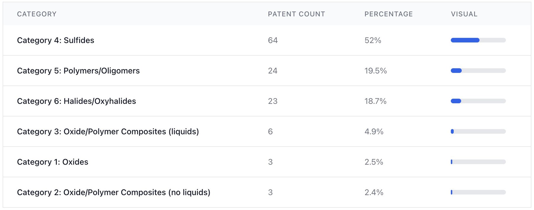
see adjacent Excel file). Sulfide, polymer and halide / oxyhalide electrolytes constitute key patenting
focus areas (Figure X-2).
Figure X-2: AI-based classification of patent families related to solid electrolyte categories.
Patents without direct relation to one category were excluded in this graph.
-
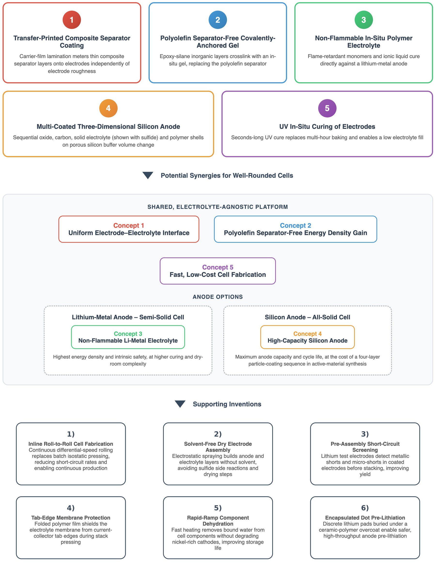
Key Product Development Concepts (see Figure X-3)
Figure X-3: AI-based semi-solid Li-ion battery product development concept identification, with potential
synergies and supporting inventions 1)–6). Publication numbers of the five concepts
and of the six supporting inventions are given in the full version.
Concept 1: Transfer-Printed Solid Separator Coating on Electrodes (EPO / Google)
KEY FINDINGS
A pre-formed polymer-film / inorganic particles (optionally ion-conducting) / adhesive composite is hot-pressed
onto electrodes then peeled, transferring a composite separator layer at controlled areal density
0.52 mg/cm2 and ≈2 μm thickness (Example 1). In full cells (Examples 7–12, 1C/1C, 100% DOD),
1,000-cycle capacity retention reaches 90.0–90.4% versus 90.3% for the conventional group (the patent's
reference cell, probably prepared by direct coating of the composite separator layer onto the electrode layer
without separate transfer). ARC thermal-runaway onset (Δt1) extends to
1,200–1,315 min versus
900 min
for the reference, and nail-penetration tolerance rises to 10–15 cathode + anode layers versus 6.
All variants pass the 140°C hot-box test.
TECHNICAL DESCRIPTION
Composite substrate = polymer film (polyvinyl butyral (PVB) / polypropylene / polystyrene) + semi-solid coating
(inorganic particles + polymer binder, 6–9.5 : 0.5–4 mass ratio; slurry solids 20–90%, viscosity ≥500 cp)
+ adhesive layer (perchlorovinyl resin / PVDF / PMMA / PAA, ≈1 μm); solid particles cover oxides
(ZrO2, γ-AlOOH, Bi2O3, GeO2, Nb2O5, plausibly
also ion-conducting oxides though not explicitly mentioned), sulfides and nanofibers. Adhesive side laminated
to cathode and/or anode; hot-press 60–500°C, 1–6,000 s (Example 1: 180°C, 30 s); polymer film peeled to leave
the coating. Example 1: ZrO2 + PMMA (7.5:2.5), PVB film, 0.52 mg/cm2, 2 μm, on
LiNi0.5Mn1.5O4 cathode.
BACKGROUND INFORMATION
The patent addresses areal-density control of semi-solid coatings: the comparative approach direct-coats the solid
layer onto the finished electrode, so the layer inherits the electrode's coating-weight fluctuation and thin
(≈2 μm) layers cannot be metered accurately on the rough surface. The comparative group therefore differs from the
transferred examples mainly at the process level – the invention casts the coating on a flat polymer carrier film
at metered areal density, overcoats a ≈1 μm adhesive layer, laminates adhesive-side to the electrode, hot-presses,
then peels the film – whereas at the material level the patent states the electrolyte composition is unchanged.
The disclosed cell data pair a conventional carbonate electrolyte (EC:DMC:EMC, LiPF6, VC) with the
transferred coating, so the tests characterize a semi-solid hybrid rather than an all-solid cell; the cycle-retention
gain over the conventional group is within noise (≤0.1 percentage point), with improvement concentrated in safety
metrics (ARC onset, nail penetration).
DEVELOPMENT OUTLOOK
The transfer-printing architecture's inherent-safety benefit is only partially realized in the disclosed cells,
which pair the transferred coating containing inert oxides with a conventional EC:DMC:EMC (1:1:1) liquid whose
DMC (≈90 °C) and EMC (≈107 °C) fractions boil well below 150 °C. The semi-solid safety advantage on which
downstream pack-level simplifications depend is plausibly captured only when every residual liquid component
boils at ≥200 °C; below that threshold the volatile carbonate fraction likely governs the thermal-runaway pathway
irrespective of the solid coating. A concrete development direction is therefore to pair the transfer-printed layer
with high-boiling-point solvent or ionic-liquid systems – extending applicability beyond the carbonate electrolytes
used in the examples and unlocking the inherent-safety benefits the architecture is positioned to deliver.
This approach remains in competition with direct printing of solid or semi-solid electrolyte layers onto
electrodes because of potential process cost savings.
ELECTRODE CONFIGURATION
Negative electrode: graphite (SBR/PVDF binder; carbon nanotube conductor) | Positive electrode:
LiNi0.5Mn1.5O4 spinel (PVDF binder, carbon black).
Concept 2: Separator-Free Covalently-Anchored Gel Architecture (EPO / Google)
KEY FINDINGS
Epoxy-silane-modified inorganic functional layers on both electrodes replace the polyolefin separator and covalently
crosslink with an in-situ-polymerized gel, eliminating the inert separator. Example 1 achieves
90.2% capacity retention after 500 cycles with hot-box failure at 180°C / 22 min. Removing the epoxy
group (control 1: propyl-silane) drops retention to 73.8% and failure to 155°C / 18 min; a non-reactive gel factor
(control 2: PMMA) gives 76.7% and 150°C / 10 min, consistent with covalent anchoring, rather than the inorganic
filler alone, being the performance driver.
TECHNICAL DESCRIPTION
Functional layer = epoxy-silane-modified inorganic particles – aluminum phosphates (ATP = aluminum dihydrogen
tripolyphosphate, AMP = aluminum metaphosphate, CAP = condensed aluminum phosphate, AHP = aluminum dihydrogen
phosphate), APP (ammonium polyphosphate), boehmite (γ-AlOOH), Al2O3, or the Li-ion conductors
LATP (lithium aluminum titanium phosphate) and LLTO (lithium lanthanum titanium oxide); D50 100–2000 nm;
silane:particle 0.5–5:100 – plus binder (PVDF etc., binder:particle 1–20 : 80–99), 2–20 μm, on both electrodes.
Gel precursor = carbonate electrolyte (LiPF6/LiFSI/LiTFSI in EC/PC/DMC/EMC/DEC) + gel factor bearing
≥2 epoxy groups (poly-GMA = poly(glycidyl methacrylate), PEG (polyethylene glycol) diglycidyl ether, or GMA
copolymers; electrolyte:gel factor 100:1–5). Example 1: ATP (D50 1000 nm) modified with
3-glycidoxypropyltrimethoxysilane, denoted ATP-EP; 80 g ATP-EP + 20 g PVDF, 10 μm layers; 1 mol/L
LiPF6 in EC:EMC:DEC (3:4:3) + 3 g poly-GMA (Mw 50,000); stacked without separator, wetted 25°C/48 h,
cured 45°C/48 h.
BACKGROUND INFORMATION
The patent addresses the residual-separator penalty of gel semi-solid cells: polyolefin separators shrink thermally
(short-circuit risk) and, when retained, add internal resistance and volume that cap energy density. Epoxy groups on
the inorganic particles and on the gel factor undergo Li-salt-initiated ring-opening co-polymerization, forming an
organic-inorganic framework that covalently bonds the two electrode functional layers (probably improving interfacial
contact and electrolyte retention while removing the inert separator). The controls establish cleanly that the retention
and hot-box gains can be attributed to the covalent anchoring rather than to the filler alone, but the electrolyte
remains a conventional carbonate system (see Development Outlook in
Concept 1).
ELECTRODE CONFIGURATION
Negative electrode: graphite (CMC/SBR; Super P) | Positive electrode:
LiNi0.8Co0.1Mn0.1O2 (NCM811; PVDF, Super P).
Concept 3: Non-Flammable In-Situ Polymerized Polymer Electrolyte (EPO / Google)
KEY FINDINGS
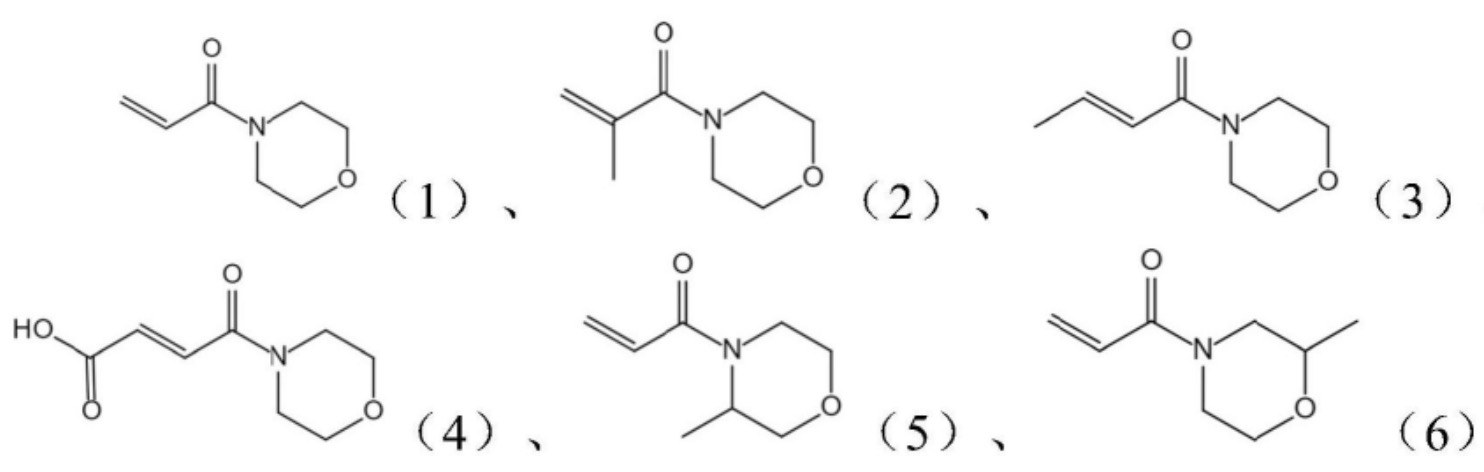
A Li-ion conducting acryloyl-morpholine monomer (Figure X-4) + vinyl-phosphate flame-retardant monomer +
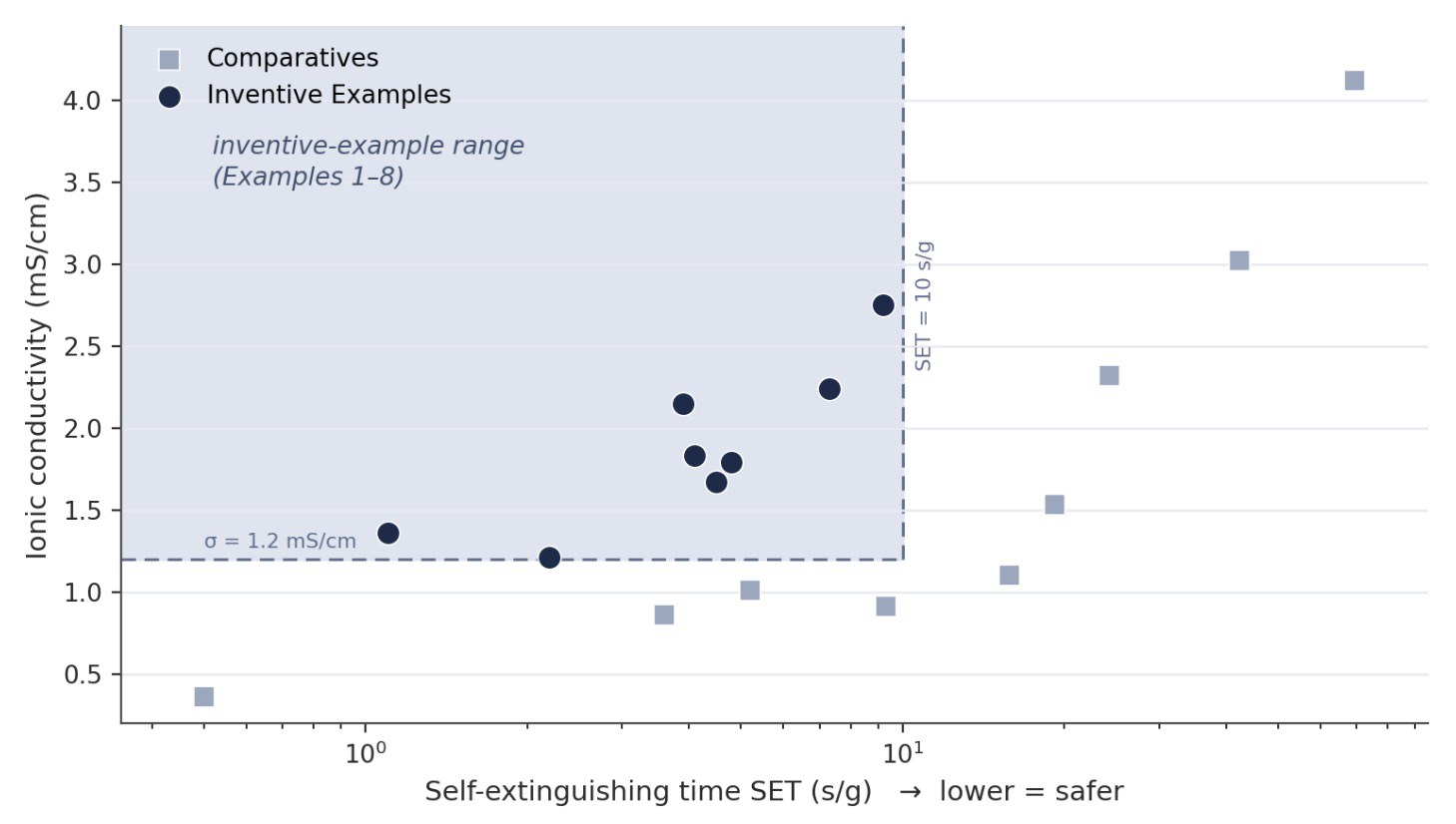
ionic-liquid system is polymerized in-situ against a 20 μm Li-metal anode. Example 2 reaches ionic conductivity
2.75 mS/cm with self-extinguishing time 9.2 s/g and holds 93.4% capacity after 100 cycles
(0.2C/0.5C, 25 °C, 2.8–4.2 V) with thermal-failure onset at 160 °C (Figure X-5); Example 1 gives
1.83 mS/cm / 4.1 s/g, and Example 3 pushes failure onset to 179 °C at 86.3% retention. A composition window
(Li-monomer + solvent = 42–75% of monomer + solvent + FR-monomer) is required: below it conductivity degrades
(control 6, 40%: 0.86 mS/cm), above it flame retardancy degrades (control 7, 80%: 24.3 s/g). A conventional
liquid-carbonate cell (control 9) illustrates the underlying trade-off, reaching 4.12 mS/cm but 69.3 s/g and
136 °C failure.
TECHNICAL DESCRIPTION
Precursor = acryloyl-morpholine Li-monomer (20–40%) + vinyl-phosphate FR monomer (e.g. diethyl vinyl phosphate,
vinyl-DEP, 20–40%) + triallyl-phosphate crosslinker (2–8%) + fluorinated sulfonylamide-anion ionic liquid
(10–18%, e.g. EMIm-TFSI) + LiTFSI/LiFSI (10–30%) + initiator (AIBN etc., 0.5–1.5%); Li-monomer:solvent mass ratio
1.2–2.9:1. Example 1: 30 g compound-1 + 30 g vinyl-DEP + 4 g triallyl phosphate + 15 g EMIm-TFSI + 1 g AIBN +
20 g LiTFSI. Precursor injected into a Z-stacked pouch (PE separator, NCM811 cathode, 20 μm Li-Cu anode) then
cured in-situ at 60°C/24 h.
Figure X-4: Acryloyl-morpholine Li-conducting monomer structures
BACKGROUND INFORMATION
The patent addresses the coupled conductivity–flammability limitation of PEO-type polymer electrolytes, whose
restricted room-temperature chain motion gives poor conductivity while the polymer itself is combustible. Morpholine
N and carbonyl groups coordinate Li+ (probably promoting salt dissociation); the vinyl-phosphate
co-monomer plausibly releases PO• at high temperature to interrupt combustion radical chains, and high crosslink
density likely enhances condensed-phase char formation. The controls are internally consistent (removing the
FR monomer, control 4: 3.02 mS/cm but 42.4 s/g; substituting carbonate solvent, control 5: 1.53 mS/cm, 19.2 s/g),
but higher ionic conductivity trades against flame retardancy across the set, and 100-cycle testing is short for a Li-metal
cell where the dominant risk is longer-term interfacial degradation.
ELECTRODE CONFIGURATION
Negative electrode: 20 μm Li-metal (Li-Cu composite) | Positive electrode:
LiNi0.8Co0.1Mn0.1O2 (NCM811; PVDF, Super P).
Figure X-5: Conductivity–flammability trade-off: ionic conductivity versus self-extinguishing time for
Examples 1–8 (in-spec) and Comparatives 1–9. Plotted from data in the patent filing, Table 1; the shaded target
region (SET ≲10 s/g) is an analyst demarcation.
Concept 4: Multi-Coated Three-Dimensional Silicon Anode (EPO / Google)
KEY FINDINGS
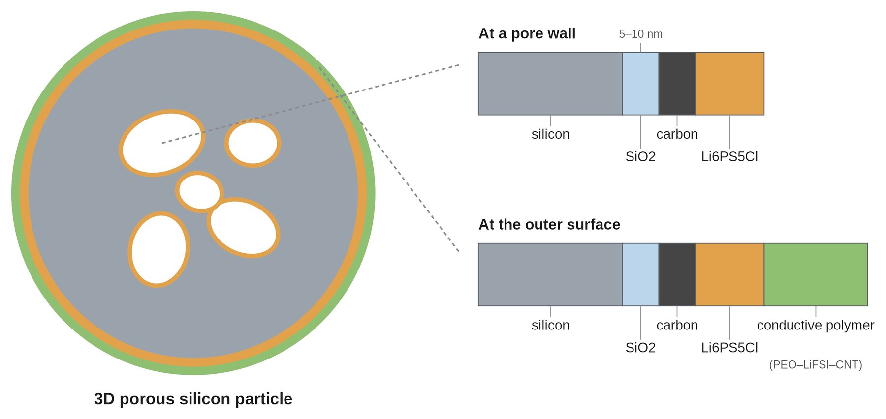
Porous silicon is sequentially coated with an oxide (SiO2), carbon, a sulfide solid electrolyte
(Li6PS5Cl) and, on particle exteriors, a conductive-polymer layer (Figure X-6). Example 3
delivers
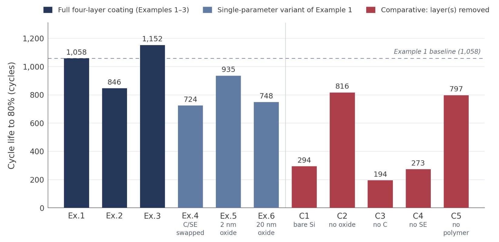
90.3% first-cycle efficiency (0.1C), 94.1% rate retention (1C/0.1C discharge) and 1,152 cycles to
80%
(1C/1C, Figure X-7).
TECHNICAL DESCRIPTION
Porous Si (D50 2–4 μm, 60–80% porosity, 0.2–0.4 μm pores; optionally Si-Cu/Si-Fe alloy) coated in sequence:
oxidation to SiO2 shell (5–10 nm; O2, 100–150 °C, 2–6 h) → CVD carbon (1–3 wt%;
CH4/C2H4/C2H2, fluidized bed 400–500 °C) → sulfide SE
(2–5 wt%; Li6-xPS5-xM1+x where M = Cl, Br and/or I and 0 ≤ x ≤ 0.6, and/or
y Li2S·(1−y)P2S5 with 0.2 ≤ y ≤ 0.8, optionally doped; fluidized-bed spray from
water, ethanol, acetonitrile or THF, then 400–500 °C / 4–12 h) → conductive-polymer layer on exteriors (3–5 wt%;
PEO/polysiloxane Mw 0.8–1.5 M + LiFSI/LiTFSI + CNT/carbon black). Example 1: porous Si, D50 3 μm, 67% pore volume,
0.3 μm mean pore size; 6 nm oxide, 2 wt% carbon, 3 wt% Li6PS5Cl, 4 wt% polymer (83 wt% PEO of
Mw 1.0 M + 15 wt% LiFSI + 2 wt% CNT).
Figure X-6: Schematic cross-section of the four-layer-coated 3D porous silicon particle: on both the pore
walls and the outer surface, the silicon core is covered by SiO2, carbon and
Li6PS5Cl layers, while only the exterior adds the conductive-polymer shell. Original
illustration (not from the patent).
BACKGROUND INFORMATION
The patent addresses the poor interfacial contact between high-capacity silicon anodes and solid electrolytes in
all-solid-state cells. Silicon's large volume change during lithiation and delithiation can disrupt electron and ion
transport paths, driving rapid impedance growth and cell degradation over cycling. The porous silicon framework
reserves internal space to buffer this expansion, while sequential silica, carbon and sulfide coatings on both pore
walls and particle exteriors – capped by an outer conductive-polymer shell – provide structural reinforcement,
electronic conduction, fast ionic channels and elastic containment of the particle. The oxide layer plausibly forms a
lithium-silicate reinforcing phase on lithiation. Coating order matters: placing the solid electrolyte before carbon
obstructs electron transport, though the measured penalty is moderate – 724 versus 1,058 cycles (Example 4 against
Example 1).
DEVELOPMENT OUTLOOK
The architecture is chemistry-agnostic – Claim 1 recites only a generic solid-electrolyte layer at 2–5 wt%, with
the sulfide formula confined to dependent Claim 3 – so the specific Li6PS5Cl choice is
plausibly revisable for a semi-solid or halide variant.
ELECTRODE CONFIGURATION
Negative electrode: multi-coated porous silicon (SiO2/C/Li6PS5Cl/polymer
coatings) | Positive electrode: NCM811 (test full cell; ternary/Li-rich/LNMO listed as options).
Figure X-7: Layer-architecture impact on cycle life to 80%: full-coating Examples 1–3; single-parameter
variants of Example 1 (Ex.4 carbon and solid-electrolyte layers swapped; Ex.5 2 nm oxide; Ex.6 20 nm oxide, against
Example 1's 6 nm); and comparatives with layer(s) removed (C1 bare porous Si; C2 no oxide; C3 no carbon; C4 no solid
electrolyte; C5 no polymer). The dashed line marks the Example 1 baseline. Plotted from data in the patent filing,
Table 1 (1C/1C).
Concept 5: UV In-Situ Curing for Quasi-Solid Cell Fabrication (EPO / Google)
KEY FINDINGS
Electrodes are UV-cured in-situ (10–180 s) instead of thermally baked (12–24 h), then dry-assembled and filled
with a fluorinated ionic-liquid electrolyte forming an organic-inorganic interface film. Example 1 (LFP) holds 87%
capacity after 200 cycles (0.5C/1C) and passes both 5 mm nail-penetration and 150°C/1 h hot-box; cell swelling force
at 200 cycles is ≈1.37 kN versus ≈3.92 kN for a liquid control. The fluorinated-IL fill coefficient
(0.8 g/Ah) is well below conventional practice (3–3.5 g/Ah for ternary, 5 g/Ah for LFP, according to the
patent filing).
TECHNICAL DESCRIPTION
Electrode material = active (70–98%) + UV monomer (1–5%; TPGDA/TMPTA cathode, HDDA/EO-BPADA anode) + photoinitiator
(0.1–3%; TPO cathode, 2-hydroxy-2-methylpropiophenone anode) + optional CNT/graphene/carbon black and
PTFE/PVDF/SBR/CMC; multi-roll transfer-pressed to 200 μm (cathode) / 100 μm (anode), UV-cured (≤400 nm,
200–700 mW/cm2, 10–180 s) under inert atmosphere. Example 1: 4.75 kg LFP + 100 g carbon black + 50 g
TPGDA + 50 g TPO + 50 g PTFE, cathode cured 400 nm/600 mW·cm-2/100 s; graphite anode with
HDDA/photoinitiator cured 200 nm/500 mW·cm-2/80 s. Dry cell filled with EMIM-TFSI/LiTFSI ionic-liquid
electrolyte at 0.8 g/Ah.
BACKGROUND INFORMATION
The patent targets the safety hazards of flammable liquid-electrolyte lithium cells while avoiding the low
conductivity, poor solid–solid contact, and difficult film formation that can limit fully solid-state cells. UV
in-situ curing polymerizes acrylate monomers within the pressed electrode at low temperature in seconds, eliminating
the multi-hour thermal bake and vacuum drying otherwise needed to remove solvent and moisture. A fluorinated
ionic-liquid electrolyte then wets the dry cell: its TFSI⁻ fluorine forms weak bonds with the acrylate ester groups
and, on decomposition during formation, yields a LiF-rich inorganic layer with an acrylate-derived organic layer.
This composite interface film plausibly combines ionic conduction with mechanical compliance, buffering electrode
volume change and improving cell safety.
ELECTRODE CONFIGURATION
Negative electrode: artificial graphite (PTFE, carbon black) | Positive electrode:
LiFePO4 (LFP, PTFE, carbon black).
-
Potential Synergies Between Concepts
The transfer-printed, composite separator coating (replacement of the polyolefin separator, Concept 1) is the
architectural hub.
A pre-formed polymer / inorganic particle / adhesive composite is hot-pressed onto the electrode and then peeled,
leaving a composite separator layer at metered areal density (0.52 mg/cm², ≈2 µm) independent of electrode roughness.
It is electrolyte-agnostic, spanning inert oxide, Li-ion-conducting sulfide and nanofiber fillers, so it likely acts as a
manufacturing platform rather than a fixed chemistry, and its process window could be what lets the electrolyte,
separator-elimination and fabrication concepts share one cell.
The coating's inherent-safety benefit is probably realized only against a
non-volatile electrolyte, which the
non-flammable in-situ polymer electrolyte
(Concept 3) could supply: an acryloyl-morpholine lithium-conducting monomer with a
vinyl-phosphate flame retardant and a fluorinated sulfonylamide-anion ionic liquid cures against lithium metal at
≈2.75 mS/cm and self-extinguishing ≈9.2 s/g. The separator-free covalent-anchoring layers (Concept 2) then allow for skipping the
polyolefin separator, as epoxy-silane inorganic particles co-polymerize with the gel to bond both electrodes
(90.2% at 500 cycles, 180 °C hot-box), while UV in-situ curing (Concept 5) replaces the multi-hour bake with a 10–180 s cure and a
low 0.8 g/Ah ionic-liquid fill.
For higher capacity, the multi-coated three-dimensional silicon anode (Concept 4) is a potential parallel route: porous silicon under
sequential silica, carbon, solid electrolyte (shown with sulfide) and conductive-polymer shells buffers volume change and
holds 1,152 cycles to 80%, with carbon placed before the electrolyte to preserve electron transport. Its sulfide coating
sits in an all-solid context, but claim 1 spans the electrolyte formula, so it potentially adapts to the platform's
semi-solid chemistry.
The lithium-metal semi-solid stack – transfer-printed interface (Concept 1), non-flammable
electrolyte (Concept 3) and separator-free anchoring (Concept 2) – favors energy density and intrinsic safety at higher curing and dry-room complexity; a graphite build on
the same electrolyte trades energy for lowest cost and process risk through the UV cure and low fill coefficient (Concept 5); and
the silicon anode on a sulfide electrolyte (Concept 4) could target maximum anode capacity and all-solid-state cycle life,
accepting the added coating sequence.
-
Possible Material / Cell / Process Characteristics
(Projection Based on Public Information)
-
Electrolyte:
Facing negative lithium metal electrode: in-situ-polymerized non-flammable quasi-solid
electrolyte from an acryloyl-morpholine lithium-ion conducting monomer with a vinyl-phosphate flame-retardant
monomer and a fluorinated sulfonylamide-anion ionic liquid (≈2.75 mS/cm, self-extinguishing ≈9.2 s/g, EPO / Google).
Separator layer: transfer-printed solid-electrolyte coating (≈2 µm, ≈0.52 mg/cm²) consisting of
epoxy-silane polymer covalently-anchored on LATP that replaces the polyolefin separator, possibly infused
with ionic liquid (EPO / Google, EPO / Google).
- Negative electrode: ≈20 µm lithium-metal foil on a copper current collector (EPO / Google).
- Positive electrode: high-nickel NCM811 with a PVDF binder and carbon black, carrying the transfer-printed composite separator interfacial coating (EPO / Google).
- Design: stacked (Z-folded) pouch cell operating at room temperature under low external stack pressure (such as <2 MPa), with a comparably low fluorinated ionic-liquid fill coefficient (≈0.8 g/Ah, EPO / Google, EPO / Google).
-
Process:
- Cast and press the high-nickel NCM811 cathode with its acrylate monomer and UV in-situ cure it under inert atmosphere (10–180 s), replacing the multi-hour thermal bake (EPO / Google).
- Coat both electrode surfaces with the epoxy-silane-modified inorganic functional layer (2–20 µm) that will replace the separator (EPO / Google).
- Transfer-print the composite separator layer onto the positive electrode by hot-press lamination of the pre-cast polymer-film, coating and adhesive composite (60–500 °C), then peel the carrier film (EPO / Google).
- Stack the printed cathode and the lithium-metal anode separator-free, inject the non-flammable precursor of acryloyl-morpholine monomer, vinyl-phosphate flame retardant and fluorinated sulfonylamide-anion ionic liquid, and cure in-situ (≈60 °C) so the epoxy layers and gel co-polymerize into a covalently-anchored quasi-solid electrolyte (EPO / Google, EPO / Google).
- Package and complete cell formation.
Supporting inventions listed in Figure X-3 (bottom) might additionally be employed in this context.
-
Excel File with AI-based Patent Summaries
The adjacent Excel file contains AI-based patent summaries for all patents mentioned in this chapter, classified in
terms of:
- Electrolyte type – see Figure X-2.
-
Patent level – level 1 (electrode / electrolyte patents) to
level 3D (manufacturing patents).
-
Development focus – electrolyte, positive electrode, negative electrode, interface / interlayer,
current collector, cell architecture, cell assembly / integration, scalable process design, production
equipment / tooling, battery pack & module design, thermal runaway mitigation, stack pressure management,
battery testing / inspection & quality control.
|