-
Lithium-ion batteries – electrolytes – solid & semi-solid
-
ALL SOLID BATTERY
Applicant:
LG ENERGY SOLUTION /
KR 20230157243 A
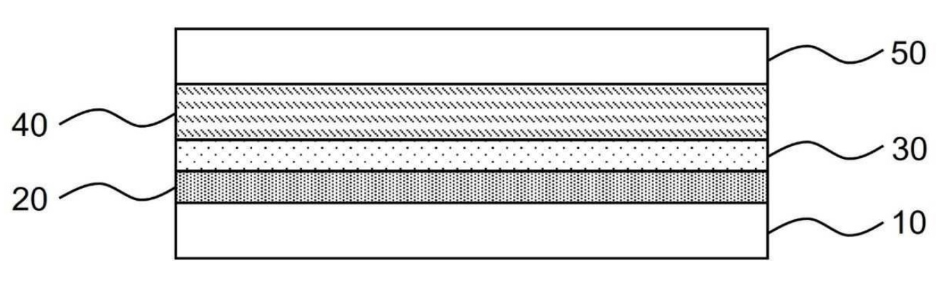
Solid-state Li-ion battery cells as shown in the Figure below were prepared through cold isostatic pressing (CIP).
10: Negative electrode – nickel current collector ('anode-free' cell design).
20: Second carbon-polymer layer (5 μm thickness) – carbon black (Super P, IMERYS), and polyvinylidene fluoride (PVDF),
95 : 5 by mass.
Coated on nickel current collector.
30: First carbon-polymer layer (10 μm thickness) – carbon black (Super P, IMERYS), and PVDF, 90 : 10 by mass.
Applied to a release film and attached to the solid electrolyte membrane.
40: Solid electrolyte membrane (100 μm thickness) – Li6PS5Cl (crystalline) and SBR (styrene-butadiene rubber),
95 : 5 by mass.
50: Positive electrode – LiCoO2 (LCO), Li6PS5Cl (crystalline), carbon black (Super C65, IMERYS), SBR,
80 : 15 : 1 : 4 by mass.
As shown in the Figure below, these cells exhibit favorable cycling stability (C-rate not disclosed), as compared
to comparative cells 1 (without layers 20 & 30), comparative cells 2 (without layer 20), and comparative cells 3 (without layer 30).
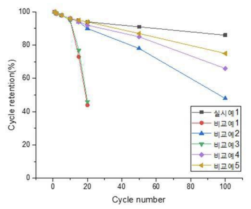
This highly relevant work illustrates how lithium metal electrodes can be very substantially stabilized if they are surrounded by
(comparably low cost) carbon black / PVDF interface layers on each side (shown in the context of sulfide electrolytes,
but probably applicable to many kinds of electrolytes).
An investigation would be very interesting to further elaborate if lithium metal deposition occurs between layers
20 and 30, and on the relative adhesion forces between the different layers, specifically between layers 30 / 20
vs. 10 / 30 vs. 40 / 30.
It appears probable that thinner carbon-polymer layers will be feasible, and that adhesion / cohesion forces between
different layers can be easily adjusted.
This favorable lithium stabilization effect might be due to a comparably high interface
area faced by the lithium metal electrode that results in a comparably low and homogeneous interface current density
(reduced risk of lithium dendrite formation).
-
The premium version includes another two patent discussions, plus an Excel list with 50-100 commercially relevant recent patent families.
-
Get a quote to make better informed decisions.
-
Lithium-ion batteries – positive electrode
-
An oxalate precursor was synthesized by mixing manganese carbonate, ferrous carbonate, cobalt sulfate,
and vanadium dichloride, followed by reaction with oxalic acid dihydrate in water.
The resulting oxalate was used to prepare the active material core
Li0.997Mn0.60Fe0.393V0.004Co0.003P0.997S0.003O4
by combining the oxalate precursor with lithium carbonate, ammonium dihydrogen phosphate, and dilute sulfuric acid, followed
by spray-drying and sintering (700°C, 4 h, nitrogen / hydrogen, 9 : 1).
Three coating layers were applied. To form the first layer, a Li2FeP2O7 solution was applied,
followed by sintering
(650°C, 6 h, nitrogen / hydrogen, 9 : 1).
The second layer was formed after dissolving lithium carbonate, ferrous carbonate, ammonium dihydrogen phosphate,
and oxalic acid dihydrate in water, followed by sintering (700°C, 8 h, nitrogen / hydrogen, 9 : 1).
Finally, a third coating was applied using a sucrose and ethylenediamine solution, followed by sintering
(700°C, 10 h, nitrogen / hydrogen, 9 : 1).
The material exhibits a discharge capacity of 159.9 mAh/g in half-cells, along with 1,169 cycles at 45°C until a capacity
retention of 80% was reached (full cells, graphite-based negative electrodes, 1 C charge / discharge).
This work illustrates how multiple dopants (V, Co, S) and a 3-layered coating allow for an LMFP material
with a capacity of about 160 mAh/g and well-rounded performance properties (specifically longevity).
-
The premium version includes another two patent discussions, plus an Excel list with 50-100 commercially relevant recent patent families.
-
Get a quote to make better informed decisions.
-
Lithium-ion batteries – negative electrode (excluding Li metal electrodes)
-
Nanosilicon powder (D50: 40-100 nm) was oxidized in air (900°C, 1.5 h). The resulting Si@SiO2
was mixed with phenolic resin (1 : 1 mass ratio), dispersed in anhydrous ethanol, ultrasonicated,
dried, ground, carbonized (800°C, argon) and milled to form a Si-SiO2-carbon material (D50: 5-20 μm).
This material was reacted with 10% HF solution and dried to produce a core-shell porous Si-carbon material.
This material was coated with a 'carbon capping' layer (800°C, mixture of argon and acetylene).
The material exhibits a Si / carbon ratio of 54.8 : 45.2 (presumably mass ratio, 0.3 ppm oxygen content) and a BET specific surface area of 2.4 m2/g.
In half-cells, the material exhibits a discharge capacity of 2,108.7 mAh/g, a first cycle efficiency of 91%, along with a capacity retention of
91.8% after 100 cycles and 91.1% after 500 cycles (100 mA/g current density).
This work illustrates how pores in silicon can be created through etching of a silicon-carbon composite material that contains a
partially porous carbon shell through which HF solution can enter.
A carbon shell that prevents access by liquid electrolyte is formed upon applying
a second carbon coating (acetylene deposition).
The comparably low BET specific surface area
and comparably high first cycle efficiency are consistent with a carbon shell that prevents liquid electrolyte from
accessing the high-surface area Si-carbon core.
-
The premium version includes another two patent discussions, plus an Excel list with 50-100 commercially relevant recent patent families.
-
Get a quote to make better informed decisions.
-
Fuel cells (PEMFC / SOFC / PAFC / AEMFC) – electrochemically active materials
-
Pt(acac)2, Ni(acac)2, glucose, W(CO)6 (mass ratio Pt / Ni / W ≈ 23 : 63 : 14), and polyvinylpyrrolidone (PVP)
were added to a mixed solvent
of oleylamine and octadecene and
subjected to ultrasonic dispersion for 30 min to obtain a precursor solution. This precursor solution was heated (140°C, 6 h).
Thereafter, it was slowly cooled to room temperature to obtain a reaction solution containing aggregates of PtNi nanowire precursors
and PtNi nanoparticle precursors, which were redispersed in hexane to obtain a first
dispersion.
Next, the carbon carrier was dispersed in hexane to obtain a second dispersion. The first dispersion liquid was added to the second dispersion
liquid and ultrasonic irradiation was performed for 1 h, thereby supporting the PtNi nanoparticle precursor on the surface of the carrier.
Then, centrifugation, redispersion in hexane, and ultrasonic irradiation were alternately repeated three times. Thereafter, filtration was performed
and the filtered material was dried.
Next, the filtrate was heat-treated (450°C, 1 h, 3% H2 / Ar).
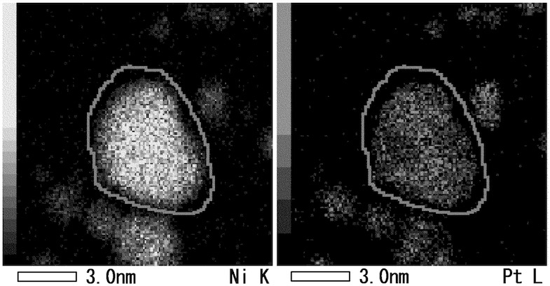
An STEM-EDX (scanning transmission electron microscopy - energy dispersive X-ray) analysis (see Figure) exhibits nanowires / nanoparticles
with a short axis of 3 nm, with an Ni / Pt molar ratio of about 3 : 1 (the Ni content in the shell is higher than in the core).
An
ECSA (electrochemically active surface area) of 39 m2/g was measured along with an oxygen reduction reaction
mass activity of 4,104 A/gPt,
as compared to 83 m2/g and 534 A/gPt for TEC10V30E (Tanaka Precious Metals, particles with a larger diameter,
as reported in the patent application).
This work illustrates how PtNi nanowires can be formed in the presence of W(CO)6, PVP and oleylamine
in the reaction mixture.
The underlying conceptual and general argument that is supported by this work is that PtNi nanowires can be expected to exhibit superior
longevity as compared to PtNi nanoparticles with similar size because of a favorable ratio
between ECSA and Pt mass activity.
In nanowires and nanoparticles with similar 'short diameter', Pt atoms are similarly close to the surface. However, the higher ECSA of nanoparticles
as compared to a nanowires with the same 'short diameter' presumably leads to faster aging of the nanoparticles.
-
The premium version includes another two patent discussions, plus an Excel list with 50-100 commercially relevant recent patent families.
-
Get a quote to make better informed decisions.
-
Triweekly patent lists for other categories (Excel files are included for premium users)
-
- Lithium metal containing batteries (excluding Li-S, Li-Air): XLSX
-
- Lithium-ion batteries – electrolytes – liquid: XLSX
-
- Lithium-ion batteries – separators: XLSX
-
- Lithium-sulfur batteries: XLSX
-
- Metal-air batteries: XLSX
-
- Na-ion batteries: XLSX
-
Prior patent updates
-
2023-12-12
-
2023-11-21
-
2023-10-31
-
2023-10-10
-
2023-09-19
|